User manual · iPhone & iPad
From belt data to a splice in the field.
Use Steel Cord Splice to prepare a design, give the crew field documents and view the construction sequence at actual size in augmented reality.
Available in 16 languages. Reference screenshots show the English iPad interface; translated control names match the selected app language.
Updated: 2026-10-17 · iPad
Version scope. This manual describes the current development version, including the new tag-free Training entry point. The product is in preparation for the App Store. An older TestFlight build may show different buttons. Screenshots are genuine iPad simulator captures; they illustrate controls and models, not a camera-verified field installation.
Here to learn field AR?
1. Practice on the floor—no printing needed
2. Place the actual job in the work area
3. Align to printed locators for repeatable placement
4. Follow both belt ends and the eleven construction steps
1. Start here
The app connects four stages: Belting → Splice Design & Analysis → Splice Construction → Splice Curing. Start from verified belt information, resolve the design, then carry the same geometry into documents and construction views.
Final dimensions must be confirmed by the belt supplier. The drawings and construction scenes explain geometry. Follow the selected supplier’s approved preparation, materials and curing procedure and your site’s work controls. AR is a visual aid; check physical lines, lengths and clearances with suitable measuring tools before transferring marks or cutting.
What you need
- iOS/iPadOS 18 or later. Camera AR needs a supported physical iPhone or iPad with world tracking; a simulator can show controls and 3D but cannot place a model in a room.
- Supplier-confirmed belt width, rating, cord count, diameter, pitch, cover thicknesses, splice pattern and materials.
- For AR: camera permission, a stationary horizontal work surface, usable lighting and room to inspect the complete splice.
- For tag placement: the correct numbered pair, an actual-size print, a tape measure and a way to keep the sheets flat and stationary.
Choose the right access
| Workflow | Access | What you see |
|---|---|---|
| Free Training | No subscription | Built-in sample 867-5309, all eleven steps, 3D and supported-device AR. No real job is assigned. |
| Main workspace design, documents and 3D | Standard or Premium | Your project. Free access retains previews, project files and existing analysis results. |
| Main workspace AR | Premium for your design | Standard shows a fixed demo. Confirm that the view is not labelled Demo before using it for a real job. |
| Received Crew job AR | Standard or Premium | The actual saved assigned revision, including construction steps. |
| Live Shared AR | Premium host; Standard or Premium guests | The host’s temporary session snapshot. |
| Combination editing, new FEA/shear-lag runs, cure simulation | Premium | Additional design and calculation tools. |
Apple’s purchase sheet shows current price, availability and trial eligibility. Premium replaces Standard; you do not need both. Job activations are separate from subscription access. See subscription terms and buying for a crew.
2. Find your way around
On iPad in a wide window, the stage selector is across the top, with inputs and the drawing or model alongside one another. A narrow window uses compact controls; on iPhone the four stages appear as tabs. Rotate the device or widen the window when you need more drawing space.
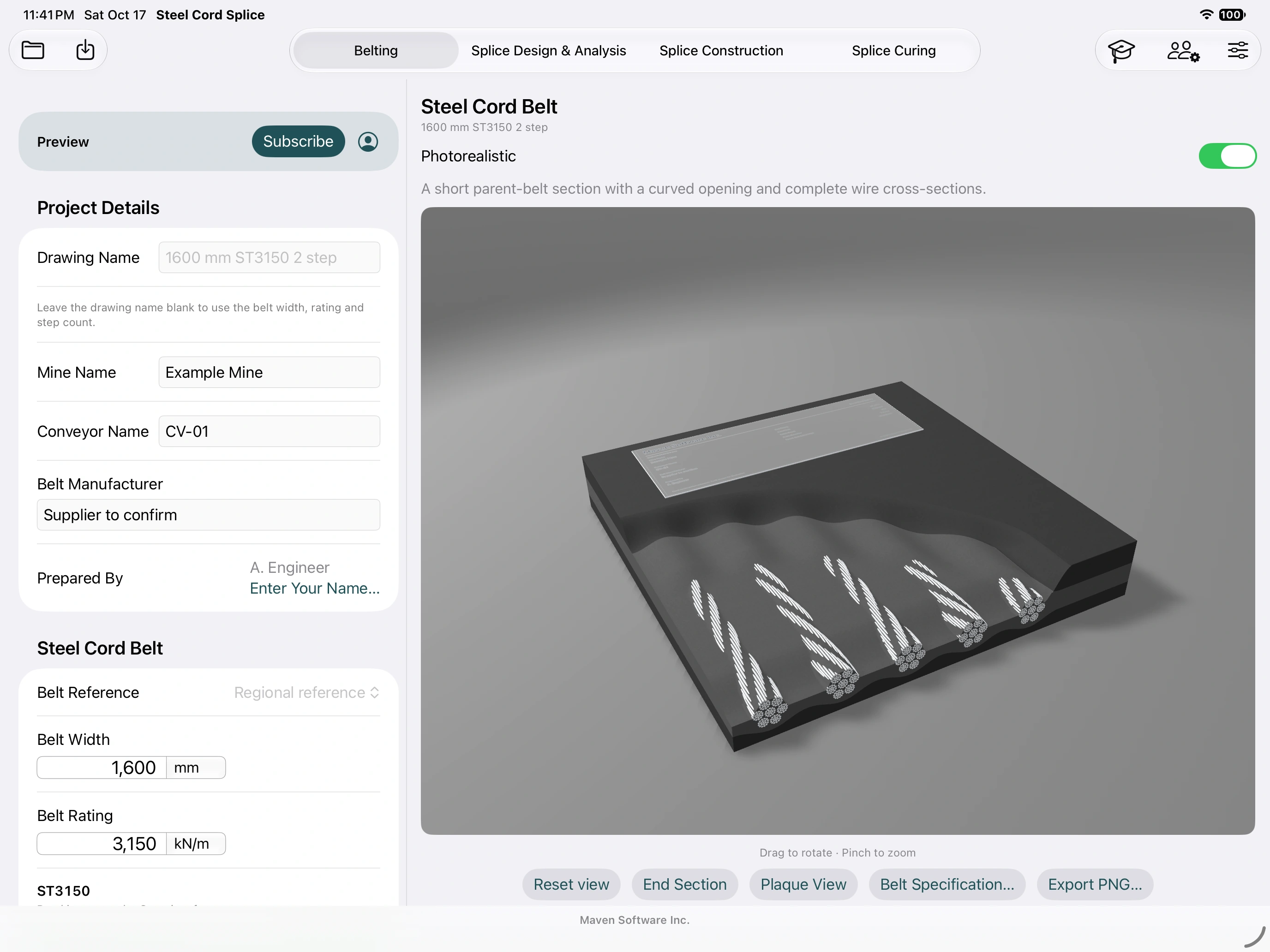
- Belting: belt construction and the parent belt cutaway.
- Splice Design & Analysis: resolved geometry, drawings, comparisons and analysis.
- Splice Construction: End A/End B preparation, assembly, cord preparation and AR.
- Splice Curing: press setup and, with Premium, a simulated heat/hold/cool cycle.
The graduation-cap Training button opens the isolated practice example. Project and account controls provide file handling, units, language, subscription and purchase restoration. Scroll the input pane to find sections below the visible area; the drawing pane has its own controls.
3. Keep projects, units and language consistent
- Enter Mine Name, Conveyor Name, Belt Manufacturer and Prepared by. These identify the job on drawings; they do not change its dimensions.
- Use the automatic Drawing Name or enter a specific one. A custom name stays fixed; clearing it restores automatic naming from the design.
- Select the measurement system and the appropriate Standard Sizes region. Confirm each displayed unit before entering or transcribing a number. Unit changes convert display values; they do not resize the physical model.
- Use Save Project As… to create a named file in Files. Choose Open Project… to reopen a saved design. Keep a separate named file for each job or approved revision.
- Save again after making changes you need to retain. Automatic recovery preserves the current workspace on the device, but is not a substitute for a named, backed-up project file.
Understand automatic values and overrides
An automatic value appears in regular type. A value you enter is an override, shown in bold. Related defaults can still recalculate behind that override. Clear an entered value to restore the current default; entering zero is not the same as clearing it. Invalid values need correction before a valid layout can be produced.
Saved projects retain resolved dimensions. Use Recalculate defaults deliberately when you want to adopt current reference defaults, then review the changed design. Older files may display a verification notice. Saving a project does not save an unsaved FEA run: analysis results have separate save/open controls.
Supported interface languages
Select the app language in Settings. The manual and app support sixteen language choices, including regional variants:
- English
- Español (Chile)
- Español (Perú)
- Español (México)
- Português (Brasil)
- Deutsch
- Bahasa Indonesia
- 简体中文
- العربية
- Svenska
- Suomi
- Polski
- Français (France)
- Français (Canada)
- Türkçe
- Русский
Controls, document text and numeric entry follow the selected language and locale. Arabic uses a right-to-left layout. Technical translations should still be checked by the crew against the supplier’s terminology.
4. Define the belt
- Open Belting. Enter width and ST rating from the actual belt specification.
- Verify cord diameter, count and parent-belt pitch. Rating-based defaults are starting estimates; replace them with the supplied construction. An even/odd preference affects an automatic count but does not replace a count you entered.
- Enter top and bottom cover gauges and review material assumptions. The cutaway helps explain the cord layer and covers; appearance settings do not change engineering dimensions.
- Use the belt specification document where available to record the resolved construction. Check it against the belt documentation before designing the splice.
For a combination splice, enable the combination option in the design workflow and enter End B’s construction separately. Premium is required to create or edit the combination. Keep each end’s count, pitch, diameter and rating tied to its own belt; do not average the two belts into one construction.
Cord preparation illustrations
Under Splice Construction → Cord Preparation, inspect the coating, knife-cut, stripped, buffed and bare-steel scenes. Drag to orbit, pinch to zoom, choose End Section for the cut face and Reset view to refit. Export PNG… records the current illustration with its explanation. These scenes illustrate material removal; their example removal percentages are not a universal preparation recipe. In particular, use piano wire only where the supplier expressly permits it.
5. Design and check the splice
- Open Splice Design & Analysis. Select the number of steps and, where offered, the cord sequence. The normal step selector offers one through five; an existing six-step reference project retains its saved geometry.
- Check step length, transition length, butt gap, clear edge rubber, bias and direction of travel. Enter supplier dimensions as overrides where required.
- If using thin and thick rubber, review both gaps and the entered placement tolerance. A calculated reference margin is not supplier approval.
- Inspect the Full, Center, Repeating and Edge patterns. Turn on cable numbers to match the field schedule. Zoom or expand the drawing for detailed checks.
- Check calculated results, actual clear cord gaps and notices. Changing step count changes overlap lanes, not the number of parent-belt cords.
- Save the checked project and export its field documents before leaving for site.
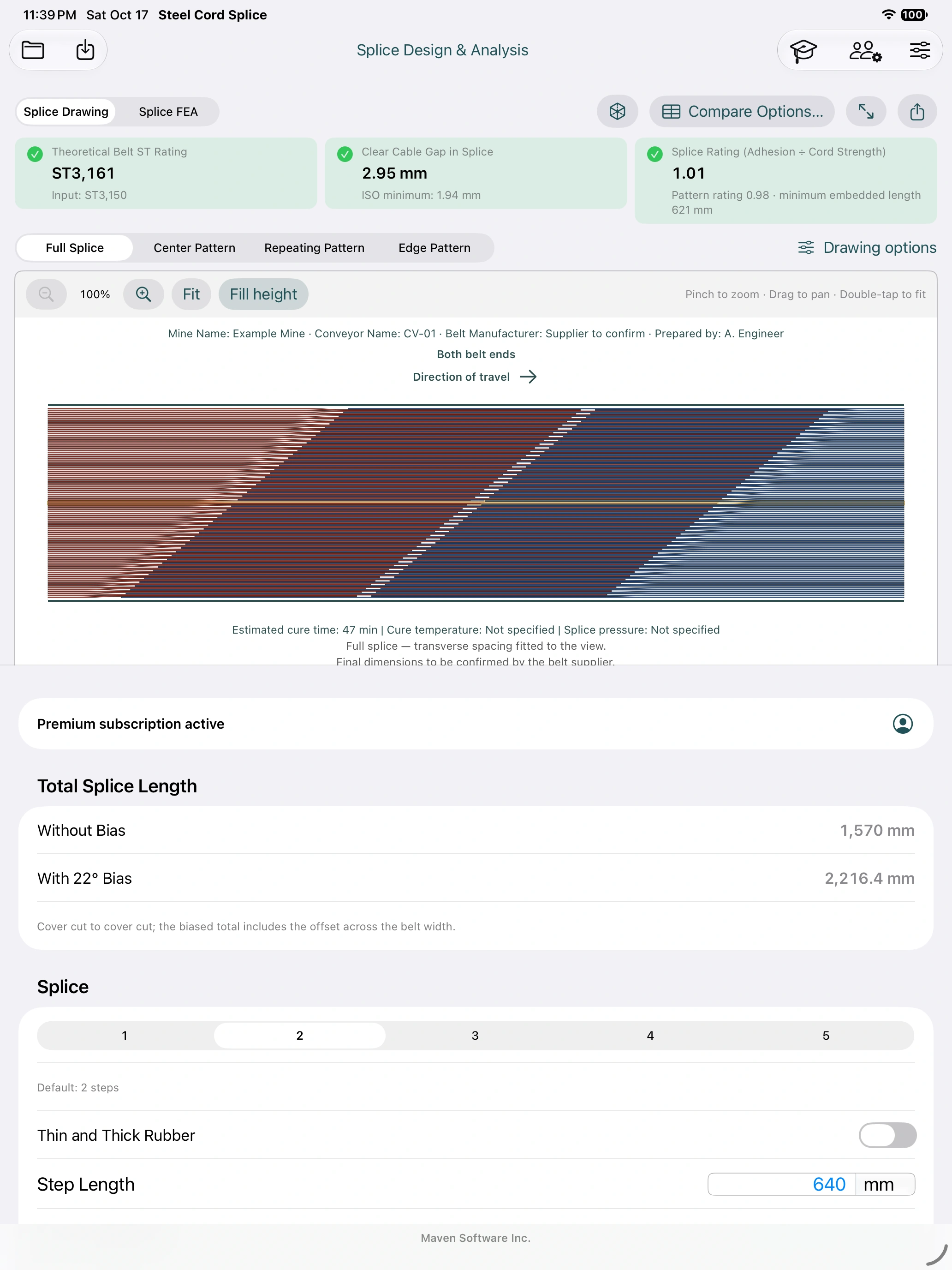
Read the drawing correctly
End A enters from the left; End B enters from the right. Parent cords are numbered from the top to the bottom of the drawing. The middle cord, or middle pair for an even count, is highlighted. Repeat counts include the illustrated block. Check center and edge exceptions as well as the repeating pattern.
The travel arrow changes with the actual cord layout: outside tips trail the direction of motion. Confirm physical travel at the conveyor before marking. End A/End B selection is a view of the ends, not a command to reverse travel.
Without bias is the cover-cut-to-cover-cut span along the centerline. With bias includes the additional longitudinal reach of the outer cover-cut corners. Do not use one as though it were the other; confirm the saved bias angle even when displaying a square drawing.
Inspect in 3D
Open Preview 3D in the 3D / Augmented Reality section. Drag to rotate, pinch to zoom and use Reset view to fit. Zooming changes the camera view, not the design dimensions. The full-splice model has no user-facing USDZ save or share operation; use the document and image exports for deliverables.
6. Prepare the field package
| Output | Use it for | Check before issue |
|---|---|---|
| Field Drawing… | Dimensioned splice layout, center/repeat/edge details and cord schedules. | Job identity, End A/B, travel, count, pattern, bias and supplier confirmation. |
| Belt End Preparation… | Separate End A and End B preparation pages; six preparation stages per end. | End identification and cut lengths measured along each cord from the cover cut line. |
| Drawing image / DXF | Image communication or CAD drawing exchange. | Dimensions and units after import. Preserve the drawing notes. |
| Belt specification | Resolved parent construction and assumptions. | Compare with the actual belt certificate/specification. |
| Materials PDF and CSV | Single-splice estimates, stock cuts and purchase quantities. | Missing inputs, stock gauges, allowances and recipe compatibility. |
| FEA result / report | Retain the calculated case and communicate assumptions and results. | Save the result data as well as the report; identify its exact project snapshot. |
Use the stage’s Export Drawing controls to open document previews, then Save PDF… or the system share/print actions. In Files, choose a known destination and reopen the saved output to verify it. A fitted field drawing is not an actual-size cutting template. Locator pages are different: they must be printed at actual size.
Estimate splice materials
- Open Splice Materials from the design inputs. Confirm the panel footprint and physical bias.
- Enter finished bonding allocations, core height where required and actual compound density data. Enter stock gauge, width, layers, trim, overlaps, allowances and roll/package sizes.
- For bonding solution, enter the actual product’s consumption per coat, coat count and container size; the app does not supply a vendor recipe.
- Review finished demand, uncured assembly volume, purchased quantity and mass separately. Blank means unknown, not zero.
- Resolve missing-input notes, then export PDF/CSV and the cut lists. Retain the calculation ID with the job package.
This is a constant-height material estimate. The app does not infer compound compatibility, compression or a complete filler recipe. Intercord run lists describe finished geometry; they are not uncured noodle widths. Confirm the supplier’s recipe and stock before ordering.
7. Walk through construction: steps 1–11
Open Splice Construction. Choose the numbered step directly or use previous/next. For preparation steps, choose End A or End B; inspect both. Select 2D/3D where offered. The instruction and scene represent the selected stage after that operation.
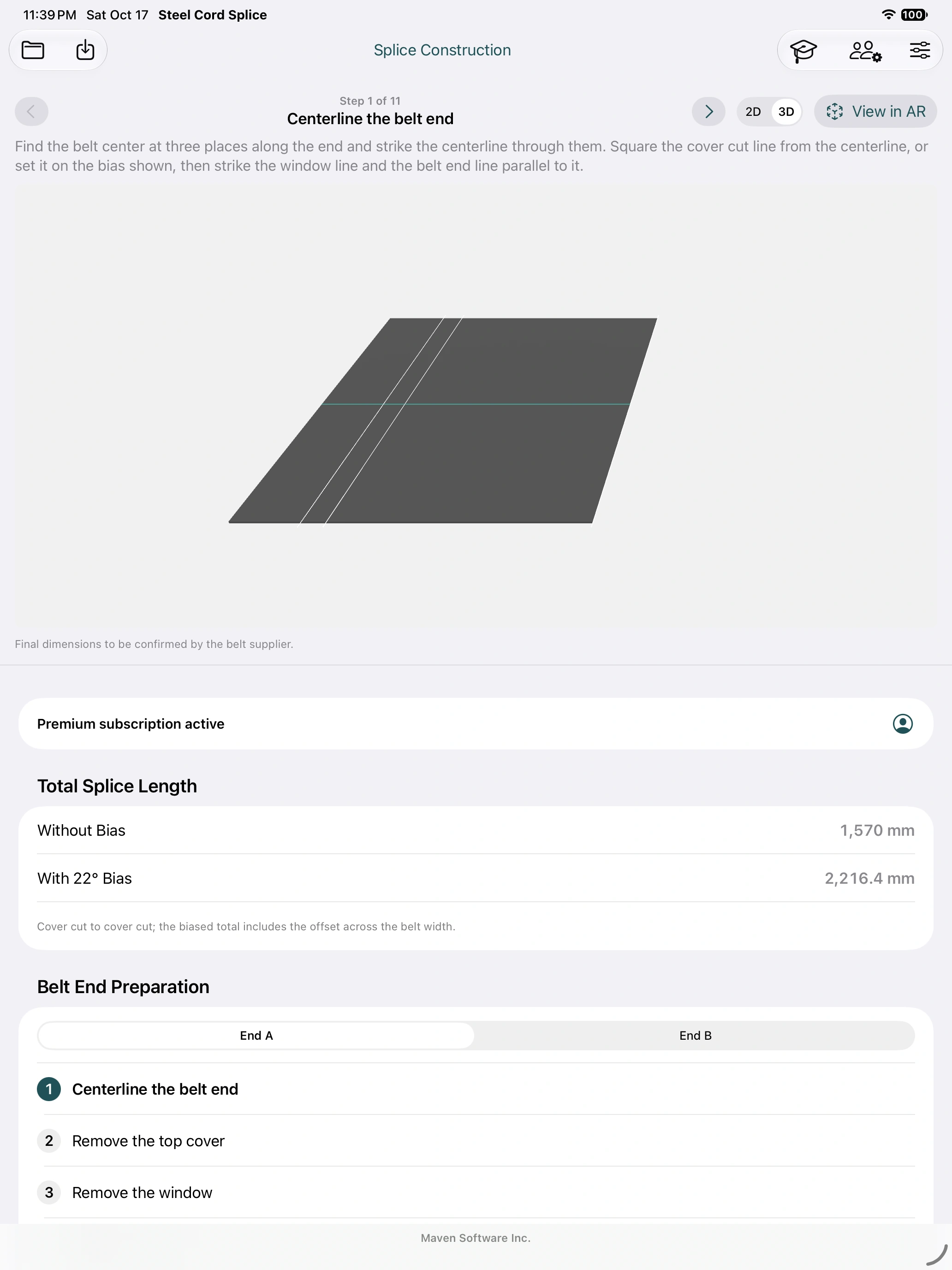
| Step | What to inspect |
|---|---|
| 1. Centerline the belt end | Centerline, cover cut, window and belt end lines; the bias follows the design. |
| 2. Remove the top cover | Top-cover removal extent, following the approved supplier procedure. |
| 3. Remove the window | Transition/window region. Removal depth and method are supplier-specific. |
| 4. Mark the cables | Color-grouped cord cut lengths. Measure along the cable from the cover cut line. |
| 5. Separate the cables | Separation and retained rubber coating as specified by the supplier. |
| 6. Cut the cables | Cut marks, end identity and offcuts; compare with the preparation sheet. |
| 7. Place the bottom cover panel | Both ends together; bottom panel between cover cuts, cords folded back. |
| 8. Lay the cables and noodles | Center-out sequence, alternating sides, and spaces between laid neighbors. |
| 9. Place the top cover panel | Top panel over the completed cable layout. |
| 10. Assemble the press | Illustrated platens, edge irons and cross beams. |
| 11. Cure the splice | Press/cure illustration. Use the supplier’s actual time, temperature and pressure. |
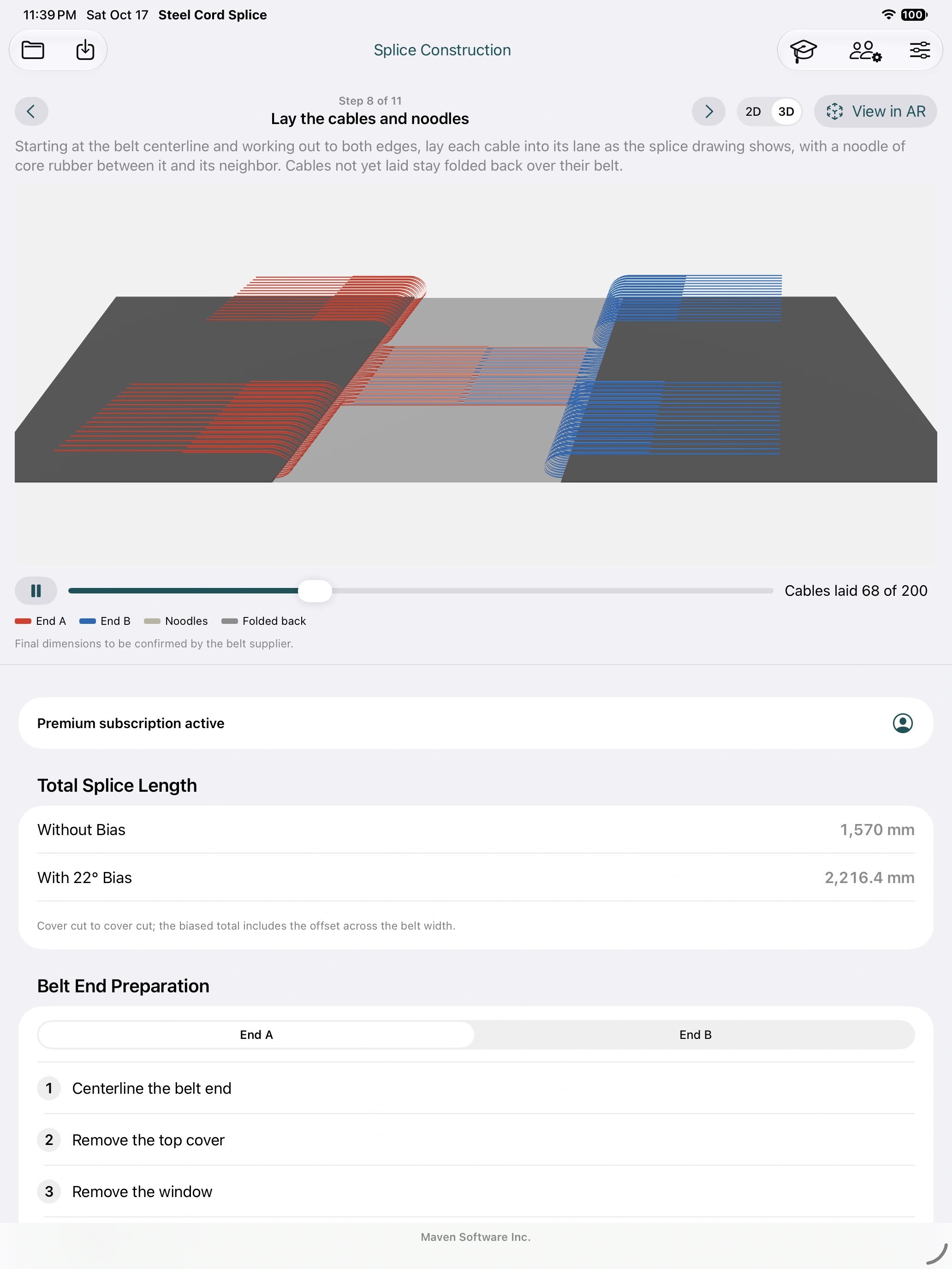
At step 8, Play animates cord laying; pause and use the progress slider/stepper to inspect individual additions. The remaining cords stay folded over their own belt in the illustration. The same numbered sequence is available in construction AR. Viewing an animation does not acknowledge a Crew revision or record that physical work has been completed.
8. First AR practice: place the sample on the floor
Start here before using a real job. You do not need QR codes, printed tags, a subscription or internet.
- Tap the Training graduation-cap button. Confirm Training splice 867-5309. This is separate from your project and does not consume a job activation.
- Tap Demo in AR Without Tags. Allow camera access when asked. Keep Locate with Tags off for this exercise.
- Aim at a well-lit floor or table. Move the iPad slowly so it can find a horizontal surface; include visible surface detail in the camera view. Wait for normal tracking and a detected surface.
- Aim at the desired splice center and tap Place Splice when enabled. The model is placed at actual size. A small table may be too small for the full sample; use a suitable floor area.
- Move around it and check the centerline, End A/End B and travel arrow. Use Reposition to choose another center, or Rotate 90° to turn it. These controls move the layout without changing its dimensions.
- Choose End A, then End B, and move through steps 1–6. Continue through steps 7–11. At step 8, play and pause cord laying or step the progress manually.
- Tap Done to return to Training. Close Training to return to your original project.
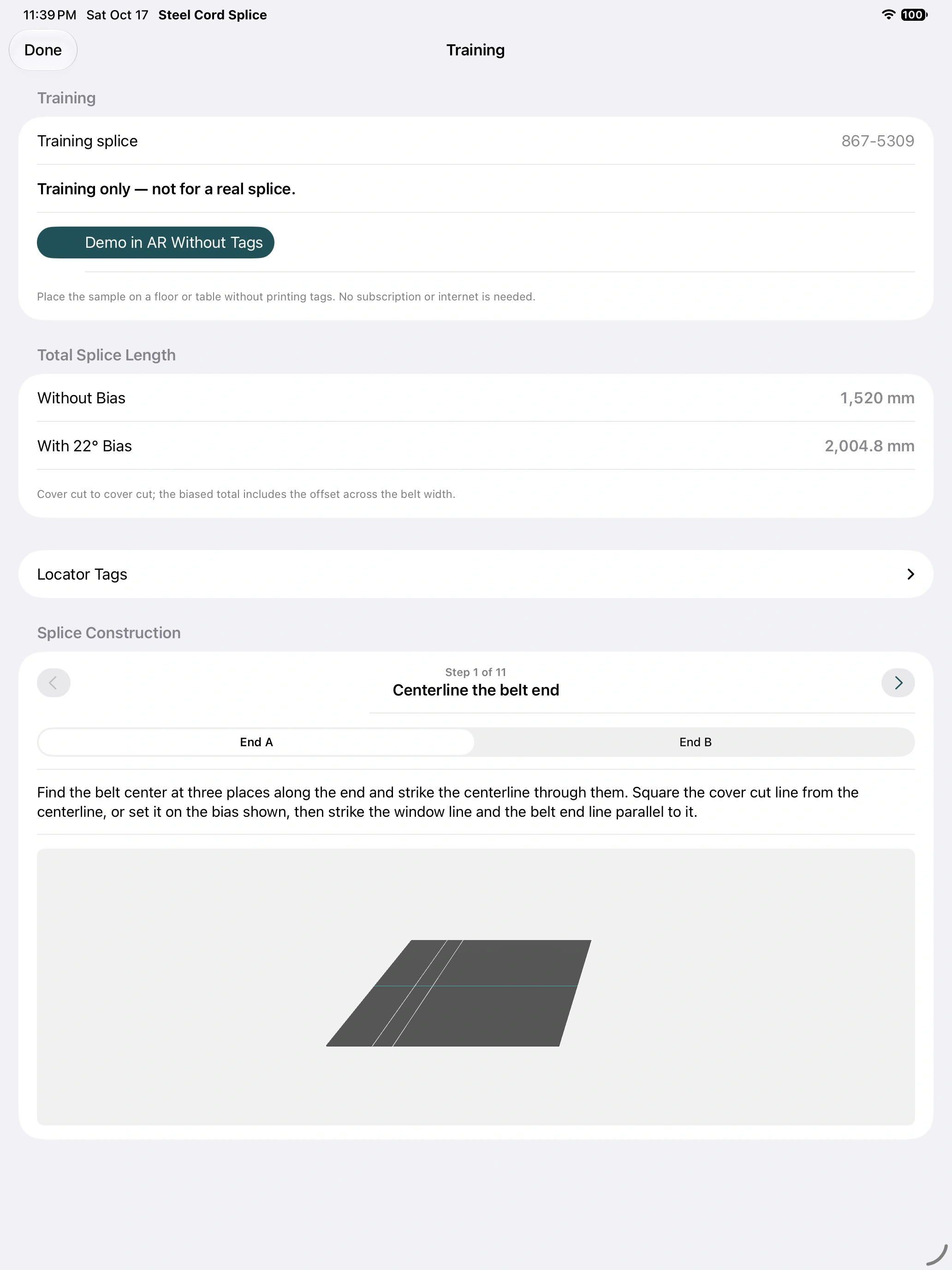
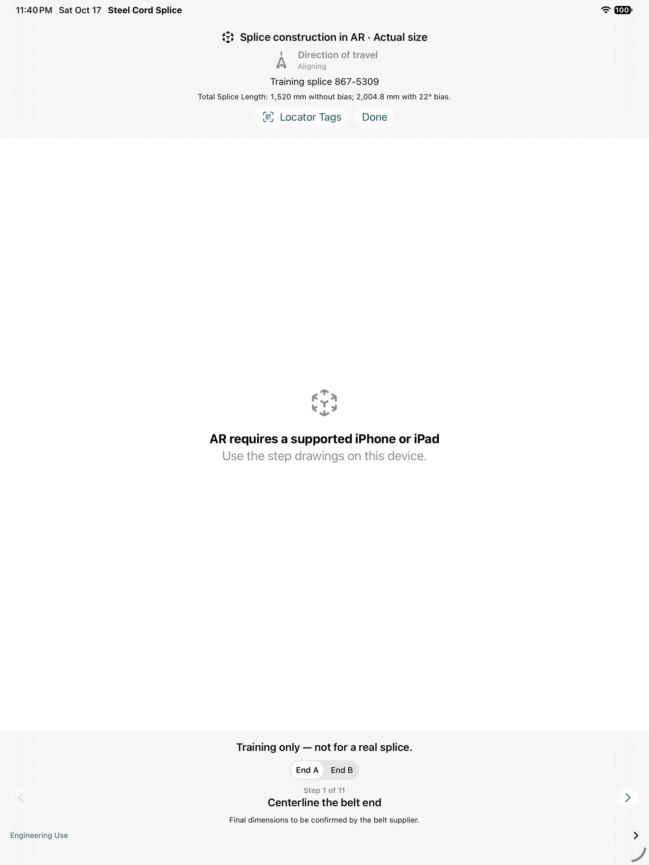
The optional Locator Tags section on the Training screen offers Print Training Tags… and View in AR With Tags. Use it after practicing the tag-free workflow. Reopening the tag-free demo explicitly chooses manual surface placement again.
9. Lay out the actual splice in the field
Before opening the camera
- Open the approved project, or open the assigned saved job in Crew jobs. Check mine/conveyor identity and the revision. The built-in Training sample and Standard’s main-workspace Demo are not the job’s geometry.
- Verify physical belt travel, belt centerline, splice center, End A/End B, bias and the full working envelope against the field drawing. Establish measured reference marks that remain available when the camera is closed.
- Choose how to align: manual floor/table placement for a visual review, or the correct pair of printed locators for repeatable alignment. Prepare the locators as described in the next section if using them.
- Open Splice Construction, select the required end and stage, then View in AR. For a received job use View saved splice in AR. Premium is required for your own design from the main project workspace.
Manual placement without printed locators
- Open Locator Tags inside AR and ensure Locate with Tags is off. Close the setup panel.
- Slowly scan the horizontal work surface. Wait for the camera and surface tracking to be ready. If Place Splice is disabled, keep scanning a detailed, evenly lit area.
- Aim at the intended splice center and tap Place Splice. Compare the visible centerline and travel indicator with the physical reference marks.
- Use Reposition if the center is wrong; use Rotate 90° for a quarter-turn. For controlled alignment to the belt centerline and travel direction, use measured locators rather than relying on an approximate manual pose.
- Walk the full length and inspect both ends. Check a separate measured reference near the far end; do not infer accuracy from a good match at the center alone.
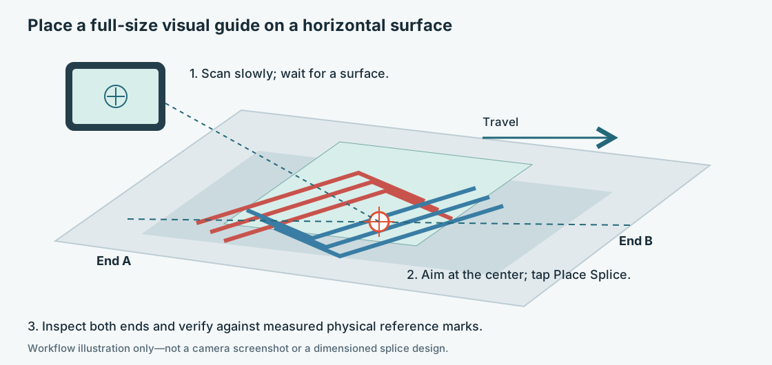
Use the overlay during the work review
Choose End A or End B for preparation, then advance through the same eleven construction steps. The construction views share a splice-center frame, so changing the end or step does not intentionally relocate the splice. The extended parent belt, surface centerline and camera-relative travel indicator help you stay oriented as you move. The red/blue cord convention in the full-splice model identifies End A/End B; preparation-stage colors group cut lengths.
Use the overlay to explain where lines, panels and cords belong, then confirm marks and lengths from the approved drawing with physical measurement. AR does not add scaling gestures, certify dimensional accuracy, establish a cutting tolerance or approve a supplier recipe.
If tracking is interrupted, the app is backgrounded or the view is closed, expect to scan and place or locate again. Check alignment after any recovery before continuing. A model that shifts relative to physical marks needs realignment, not a compensating change to engineering dimensions.
10. Align using printed locator tags
The small QR code identifies or helps receive the job. The large tracking images establish placement. A QR scan alone does not align the model, and an identifier alone cannot supply an uncached design to an isolated device.
Print and place the correct pair
- For practice, expand Training → Locator Tags → Print Training Tags…. For your project, use Print Locator Tags… from locator setup. For an assigned Crew job, use its permanent purchased/assigned pair. Training tags cannot locate a real design.
- Print both pages at 100% / actual size. Disable Fit to Page. Check the printed 100 mm bar with a ruler; each large tracking image is 150 × 150 mm. Keep the identifying labels and arrows intact.
- Use one tag I and one tag II from the same pair. Two copies of tag I do not make a pair. Do not substitute the separate Shared AR alignment-check target.
- Fix both sheets flat and stationary. Put their centers on the belt centerline, equally far from the splice center on opposite sides. Both arrows point in the physical direction of travel. Either numbered tag can be on either side.
- Use the app’s recommended distance as a starting position: it puts each tag center 200 mm beyond its cover cut along the centerline. Then measure the actual center-to-center spacing with a tape.
- Enter Actual distance to each tag as half the measured total. Both physical halves must be equal. For example, a total of 2.400 m means 1.200 m to each tag—not 2.400 m in that field.
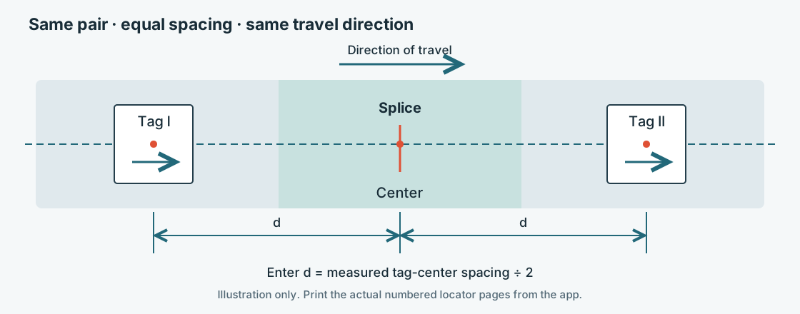
Configure and acquire the tags
- For Training choose View in AR With Tags. In a job’s AR view open Locator Tags and turn on Locate with Tags.
- Set Tags are on the belt’s top cover only when that describes the physical placement. Turn it off for a floor or bench. This setting affects vertical placement.
- Check the actual per-tag distance. If correcting it inside AR, enter the tape measurement and tap Apply, then close locator setup.
- Look at each large image in turn, keeping it readable and unobstructed. Wait for both detected indicators and acceptable spacing/arrow alignment. Correct the physical pair or entered distance if the app reports a mismatch.
- Compare the resulting overlay with measured centerline and travel references, including the far end. Use Relocate to acquire placement again after moving the setup or recovering tracking.
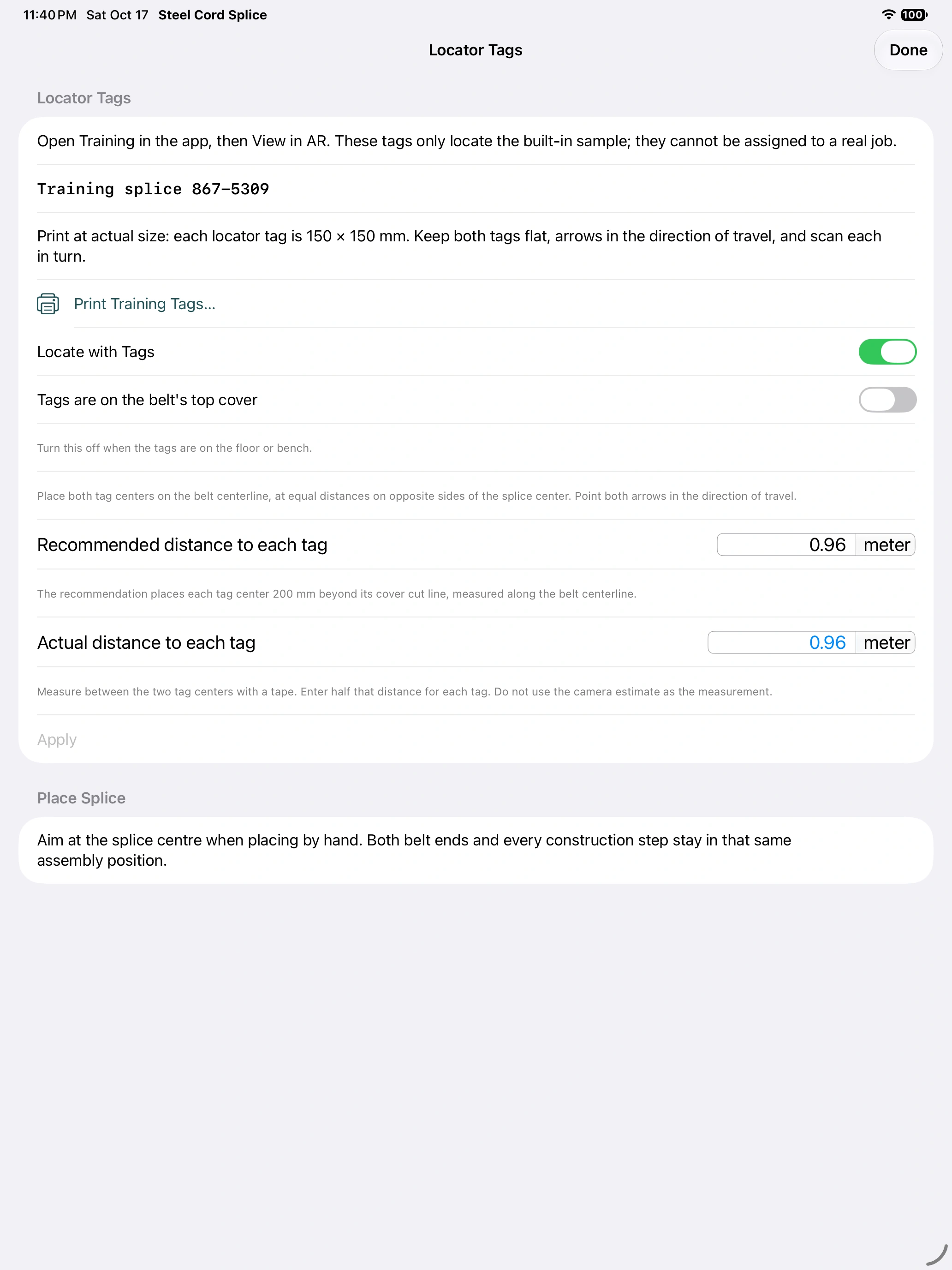
Tag placement fixes orientation from the pair, so manual Rotate is not offered in tag-located mode. Correct the physical arrows and centers rather than rotating the drawing independently.
Training example dimensions
The built-in 1200 mm sample recommends 0.960 m to each tag, or 1.920 m between centers. These are sample values, not dimensions for your job. If using another equal spacing, enter its actual measurement. The camera spacing estimate is feedback; it is not a substitute for the tape measurement.
11. Give the crew the exact job revision
Crew jobs saves an assigned design on the worker’s device. It is separate from a temporary Shared AR session. Standard and Premium support received-job AR and the supervisor workflow with suitable tag stock.
Supervisor
- While online, open Crew jobs and enter your name and crew/company identity. Under Splice activations, buy/restore available credit and Prepare one tag pair, or import supplied private tag stock through Import tag order. Print and retain the matching pair.
- Open the correct approved project. Under Supervisor · Tag inventory, select the reserved pair and Start Splice.
- Confirm site, conveyor, boundary radius and location, or record why location is unavailable. Enter the actual measured per-tag distance. Starting assigns the pair permanently to this job and starts its 48-hour window immediately, including offline.
- Open the job and select Share with Crew. Keep that screen open and Wi-Fi enabled while workers receive it.
- Review the receipt log. Received and saved, Opened and Acknowledged are distinct events for a particular revision. Pending is not confirmation of delivery.
- When the approved design changes, publish the revised main-workspace design to the same job. Have each worker receive and acknowledge the new revision. Record extensions with reasons and complete the job when finished.
Worker
- Open Crew jobs, enter your identity and scan the small QR on a job tag or the supervisor’s sharing screen.
- Receive from the registry when online or from the nearby supervisor. Keep Wi-Fi enabled and allow Local Network access. A site Wi-Fi network and internet are not required for nearby transfer.
- Confirm job identity and revision, open the saved instructions and acknowledge the correct revision when reviewed.
- Choose View saved splice in AR. Scan the pair’s large tracking images to align, then use both ends and all eleven steps. The saved job is separate from your open project.
If an unfamiliar job QR is scanned inside AR, use Find Splice, ask the supervisor to open Share with Crew and receive the design. Use Try Again if needed. Ordinary project tags lead to live Shared AR guidance; they do not create a durable assigned Crew copy.
Activations, expiry and offline preparation
Preparing a pair spends an activation; reprinting does not. The current launch offer provides a single activation purchase; trust the products actually offered in the app. Premium’s two included activations are granted once after the first paid charge, not during a free trial or at each renewal. Included credit has a 90-day activation deadline; purchased credit has no activation expiry.
Prepare/reserve stock and check subscription access before leaving connectivity. A used pair cannot be reassigned to a different splice. Job-window expiry stops new active local hosting but does not erase saved instructions or history. Opening Crew jobs still needs an active Standard or Premium entitlement. Offline use is not a promise that StoreKit verification will remain valid indefinitely.
Crew names are self-entered. Device receipts distinguish delivery and review events; they do not authenticate employee identity or prove physical installation completion. Keep private reservation/order files with the supervisor.
13. Compare and analyze designs
Compare Options
- Open Compare Options… in the analysis section. It snapshots the belt without changing your project.
- Select the length basis: Same step length, Same splice span or Default by step count. Check how that choice affects the candidate dimensions.
- Inspect sequences, preview geometry, cord gaps, edge clearances and placement-tolerance effects. The parent width, count, diameter and pitch remain fixed.
- With Premium, use the shear-lag screen to narrow candidates, then run FEA on selected cases. Do not treat a screening rank as an approved splice strength.
Run FEA
- Select Splice FEA and verify applied tension, cord axial stiffness/steel inputs, rubber modulus and Poisson ratios, parent length, mesh size and far-field condition. The initial load is an assumption, not a measured operating tension.
- Choose Run FEA. Correct invalid geometry or resource-limit messages before retrying. A finer mesh can require substantially more memory.
- Review cord force/ratio, rubber stress and mid-plane shear strain, extension, load distribution and numerical checks. Check the plotted field and color scale; a shared p99 scale can saturate higher peaks.
- Refine the mesh and compare relevant results before interpreting small differences. Sharp cord-tip peaks depend on the mesh.
- Save the analysis result separately. Export a report PDF, image or CSV where offered. Retain the full result data with the report and the input project.
The FEA uses a two-dimensional linear-elastic, perfectly bonded approximation. It does not model fatigue, debonding, damage or certify strength. The reported far-field choice matters; saved historical results may use a different one. Existing saved results can be opened and viewed without Premium, but new calculations require Premium. Changing or losing Premium prevents new runs and stops an ongoing run.
14. Set cure instructions and inspect the press cycle
Record supplier cure settings
In the design inputs, Splice Cure records temperature, optional tolerance, joint pressure, timer start and cure hold. The initial time rule is 3 minutes per millimeter of finished thickness, rounded up; replace it with the supplier’s required time. Clearing an entered cure time restores the estimate.
An optional additional heat-up dwell has its own temperature and duration. Heat-up, that dwell and cooling are separate from the main cure hold. A zero or unset dwell duration omits it from the drawing note. Check the cure block on the exported field drawing, including any unspecified supplier values.
Use Splice Curing
- Open Splice Curing. Review the press and belt geometry against the physical equipment.
- Set heater output and corner behavior, cooling water/pump assumptions, pressure bag, edge bars, altitude, ambient conditions and any heat-up hold.
- With Premium, run the heat-up, cure and cooling simulation. Inspect temperature/cure distribution, including the least-cured regions, before comparing setup alternatives.
- Retain the supplier-approved production settings with the job documentation. Use the press’s actual controls and records to perform and document the physical cure.
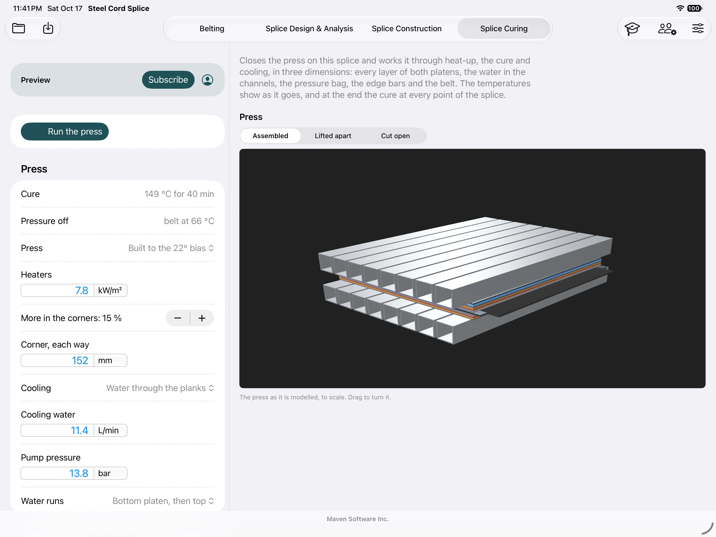
The simulation is an engineering estimate under its entered thermal and equipment assumptions. It does not operate a physical press, supply an approved recipe or replace measured production temperatures, pressure and timing.
15. Troubleshooting
| Symptom | What to do |
|---|---|
| Place Splice is disabled | Use a supported physical device, allow Camera in system Settings, scan slowly and wait for a detected horizontal surface and normal tracking. Try a better-lit, more detailed surface. |
| No camera AR in the simulator | Expected. Use Training/3D for interface practice, and a physical iPad/iPhone for placement. |
| Wrong design / Demo banner | Exit and confirm entry point. Free Training is fixed. Standard main-workspace AR is a demo; use Premium for your project or open the actual received Crew job. |
| Only one tag detected | Scan both large images in turn. Use I and II from the same pair, flat, actual size, readable and unobstructed. Reduce glare and check the 100 mm printed bar. |
| Spacing or arrow mismatch | Measure center-to-center with a tape, divide by two, enter the actual per-tag value and Apply. Put both centers on the centerline, equally spaced about the splice center; point both arrows along travel. |
| Model height seems wrong | Check Tags are on the belt’s top cover. Turn it off for a floor/bench. Reacquire and compare physical references. |
| QR recognized but job unavailable | The code is an identifier. Ask the supervisor to open the job’s Share with Crew, enable Wi-Fi/Local Network, then Find Splice or Try Again. An isolated device needs the design transferred first. |
| Model drifts or vanishes | Recover stable tracking, then Reposition or Relocate and check near/far physical references. Do not change design dimensions to compensate. |
| Rotate is missing | Tag mode derives orientation from the pair. Correct the physical tag setup. In Shared AR only the controller can alter placement. |
| Shared AR connected but not aligned | Scan the host’s area for room mode, or both matching locators for construction mode. Wait for Aligned and verify both devices are in the same view type. |
| Session ended after switching apps | Return, host/join again and realign. Use a saved Crew job for instructions that must remain after live sharing ends. |
| Values change unexpectedly—or stay fixed | Review defaults versus bold overrides. Clear an override to use its current default. Check units and the selected reference region. |
| Missing materials quantities | Read the missing-input notes. Enter actual stock/recipe data; blank means unresolved, not zero. Correct incomplete numeric entries before exporting. |
| FEA cannot run | Check Premium access, valid geometry/material inputs and mesh/resource notices. Increase target mesh size when appropriate, then review convergence before relying on results. |
| Purchase access is missing | Use Restore Purchases with the purchasing Apple Account and connectivity. Manage subscriptions through Apple. Subscription restoration and activation preparation may need internet. |
| Older job revision appears | Compare revision identity with the supervisor, receive the new revision and acknowledge it. Existing worker copies are not silently replaced. |
16. Quick reference and support
| Term | Meaning |
|---|---|
| Parent cord count | Cords in one belt end; distinct from occupied splice lanes. |
| Cover cut / window line | Start of transition / one transition length toward the belt end. |
| Cut length | Distance along the cable from the cover cut, including its transition path. |
| Actual distance to each tag | Splice center to either tag center; half the total tag-center spacing. |
| Training | Reusable isolated sample 867-5309; no real-job activation. |
| Crew job | Assigned, saved design snapshot with revision history and receipt log. |
| Shared AR | Temporary nearby live session; the controller guides shared placement/progress. |
Before going to site
- Save the approved project and field package; check they open on the working device.
- Confirm the actual job/revision and paid access. Reserve/prepare needed tag stock while online.
- Print the matching pair at actual size and verify the 100 mm bar.
- Practice camera permissions, training placement and local crew transfer before the shift.
- Carry the approved supplier procedure and physical measuring tools.
To keep a printable copy of this manual, use the browser’s Print → Save as PDF. Its print layout omits navigation. Open screenshot links individually to inspect fine controls.
For help, email support@mavensoftware.ai. Include app/build version, iPad/iPhone model, OS version, workflow, exact message and steps to reproduce. For AR issues include placement mode, measured tag spacing and whether tags were on the top cover or floor. Remove confidential job information from files and screenshots before sharing.
Product support · Privacy · Engineering use and terms
Back to top ↑