Visual motor engineering · Current release for Mac and Apple Vision Pro
See the motor.
Understand the field.
Learn how motors work and explore early design choices in a visual engineering studio for students and independent engineers. Investigate permanent-magnet and induction motors, fields, transients and engineering results.
Available now on the App Store for Mac and Apple Vision Pro. Check Apple’s compatibility section for the current supported platforms and OS versions. Explore included examples for free; Pro unlocks custom designs and analyses.
Download Motor Maven on the App Store
Explore for free
Included examples, example field and performance inspection, RealityKit motor visualization, reference citations and model notes. Build, edit, search, import and export your own reusable material library.
Design with Pro
Edit custom motors, run nonlinear and 3D electromagnetic analyses, simulate stationary-rotor induced currents, compare designs and apply steel, magnet and conductor materials as project snapshots, and export engineering reports and numerical results.
Motor Maven on Mac
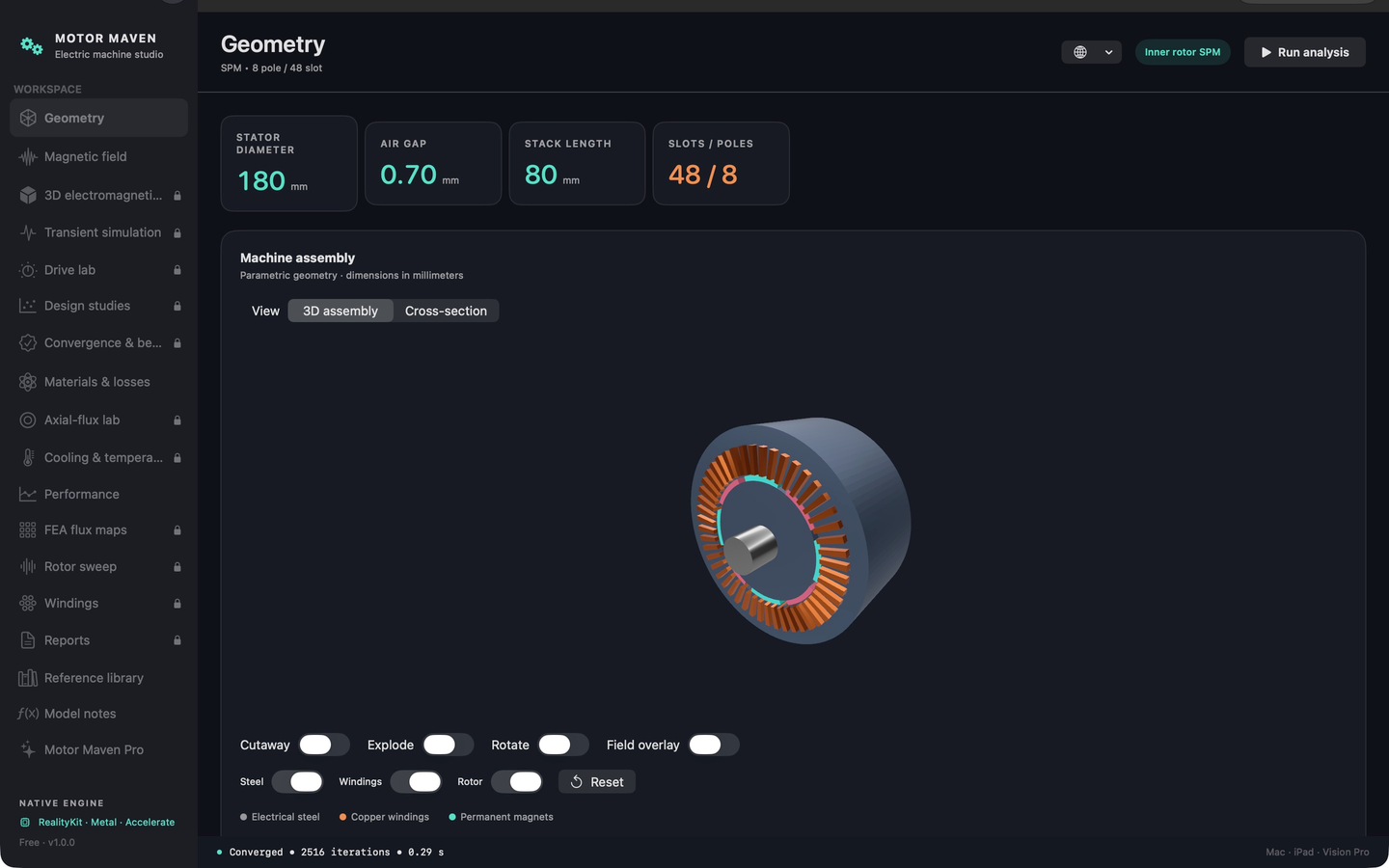
The Mac release joins Apple Vision Pro. Explore included motors for free, inspect the geometry and 3D assembly, and use Pro for custom designs and analyses.
Worked engineering example · Development app
Escondida thesis-based gearless drive example
What happens when a large conveyor pulley bends its shaft and moves the motor rotor off-center? A smaller gap changes the magnetic attraction, which changes the deflection again. This example follows that feedback from an electromagnetic reference to the clearance at both ends of the motor.
The motor template follows Galasso Hofer’s study of gearless overland drives at Minera Escondida, Chile. This example combines that template with an illustrative shaft layout and assumed masses and support stiffnesses. It is an educational sensitivity model. The motor's force disagreement with the Galasso Hofer thesis remains unresolved.
Pulley-body stiffness is not calculated explicitly. For now, the example assumes 40% of bending moment passes through the pulley body and 60% through the shaft between the two hub centers. This is a user-selected allowance, not a published result or a calculated shell, end-disk or hub stiffness. Full belt, gravity and magnetic loads remain applied.
Build the Andersen mill-drive benchmark
Andersen’s Danish thesis studies a gearless mill drive. Sum the responses of 60 uniformly spaced poles using Andersen's published attraction of 259.9 kN per pole and attraction derivative of 8,518.47 N/mm per pole at maximum torque. The centered net pull cancels; the derived lateral sensitivity is 255.554 kN/mm. This analytical aggregation checks signs, units and force summation. It reproduces the published linear response approximation. A separate standalone Andersen motor example now uses the thesis’s geometry dimensions and winding table with documented approximations. Its native field calculations are separate from this published-response benchmark; quantitative thesis agreement is not established.
Calculate this motor's magnetic stiffness
The nonlinear field model differentiates force at fixed current in both transverse directions. For the 16-pole, 144-slot motor at 165.9 A field current and zero stator current, centered sensitivity is 113.865 kN/mm. At 3 mm eccentricity, the tangent in the displacement direction is 101.895 kN/mm. The pulley calculation uses this motor's computed force map.
Couple the magnetic pull to the pulley supports
A beam model of the shaft, assumed 40% body moment share, bearing springs and stator supports solves the rotor's translation and tilt with magnetic force and bending moment. Under the default belt load and gravity, magnetic feedback reduces minimum clearance by 0.216 mm. The computed equilibrium has positive incremental stiffness within this static model.

Inputs, numerical checks and model scope
The shaft layout uses a 6,197 mm overall length, bearing stations at 1,890 and 5,090 mm, and hub loads at 2,598.5 and 4,381.5 mm. The 3,645 kN fatigue belt resultant comes from the anonymized structural reference, Issue 2 (May 2026), Appendix D and Table 1.
Example assumptions are a uniform 860 mm steel shaft with E = 210 GPa, equal hub load split, a 20 t rotor, a 50 t pulley, rotor attachment at 900 mm and a 1,400 mm active motor length. Each bearing has 2,000 kN/mm translational stiffness; the stator has 1,000 kN/mm translational stiffness and 1012 N·mm/rad rotational stiffness. Shaft self-weight is included separately. Missing pole details and the FEMM M-45 reference steel curve are documented in the native input.
The moment-share allowance applies only from hub center 2,598.5 mm to hub center 4,381.5 mm. The equivalent rigidity there is EI_total = EI_shaft / (1 − share); at 40%, it is 1.667 times shaft rigidity. Body and shaft moments are 40% and 60% of the total respectively. Outside this span, the shaft retains its original rigidity. External forces are not reduced.
In this example, stiffening the span between hubs changes overhang translation and tilt and slightly reduces motor clearance. The 0% case is retained for comparison; increasing body rigidity does not guarantee a larger air gap.
| Body / shaft share | Unenergized minimum gap | Coupled minimum gap |
|---|---|---|
| 0% / 100% | 7.099 mm | 6.900 mm |
| 40% / 60% (default) | 7.076 mm | 6.861 mm |
| Field current | Centered | At 3 mm eccentricity |
|---|---|---|
| 0 A | 0 kN/mm | 0 kN/mm |
| 100 A | 81.13 kN/mm | 105.96 kN/mm |
| 165.9 A | 113.87 kN/mm | 101.89 kN/mm |
| 474 A | 54.23 kN/mm | 55.87 kN/mm |
The derivative uses central perturbations of 0.05 mm. Doubling the step changes centered Kxx by 0.113%; Standard mesh gives 114.712 kN/mm, 0.744% above Draft. These are local numerical consistency checks. They do not establish agreement with the complete thesis or the installed drive.
The model uses an Euler–Bernoulli shaft, a rigid rotor and a radial force map with no extrapolation. Three axial integration points account for motor tilt. Shell, end-disk and locking-device stiffnesses are not calculated explicitly; the moment-share allowance replaces their combined bending contribution between the hubs. Local ring distortion, shear, thermal expansion, axial magnetic force, drive torque, stress, fatigue, vibration and startup dynamics are outside its scope. The positive clearance is a result for these assumptions, not a design acceptance assessment.
Source theses and downloadable reference data
Søren Bøgh Andersen, DTU, 2012: Design and Optimization of Gearless Drives using Multi-Physics Approach, Tables 3.2 and 6.8, supplies the separate pole-response benchmark.
Simón Ignacio Galasso Hofer, 2018 thesis identifies the Escondida OGP1 conveyors CT-236, CT-237 and CT-238 on printed pp.1-2; Table 3.1 and Appendix A supply the conveyor motor template. Assumed geometry and the unresolved force comparison are retained in the example notes.
The download includes the native input, source and assumption records, Andersen benchmark, magnetic force map and stiffness checks, coupled result, shaft deflection and both-end clearance CSVs, shaft/body bending-moment CSV, 0/20/40/60% moment-share comparison records, and the plot. The source report PDFs are retained with the local project documents.
Moment-share comparison (CSV) · Shaft/body bending moments (CSV)
Source and assumption record (JSON) · Numerical reference checks (JSON) · Andersen mill-drive benchmark (JSON)
Try the example in Motor Maven
In the development app, open Examples → Thesis examples → Escondida thesis-based gearless drive example, then select Calculate stiffness and coupled deflection in the Wound-field lab. The unchanged bundled example is free to analyze; edits and numerical exports follow the app's Pro policy. You can also open the downloadable native project.
Standalone motor example · Development app
Andersen 2012 gearless mill-drive motor
Explore the large ring motor in Søren Bøgh Andersen’s Danish DTU thesis as its own native project. Inspect its salient poles and field coils, calculate a static magnetic field, and change eccentricity to examine the air gap and magnetic pull.
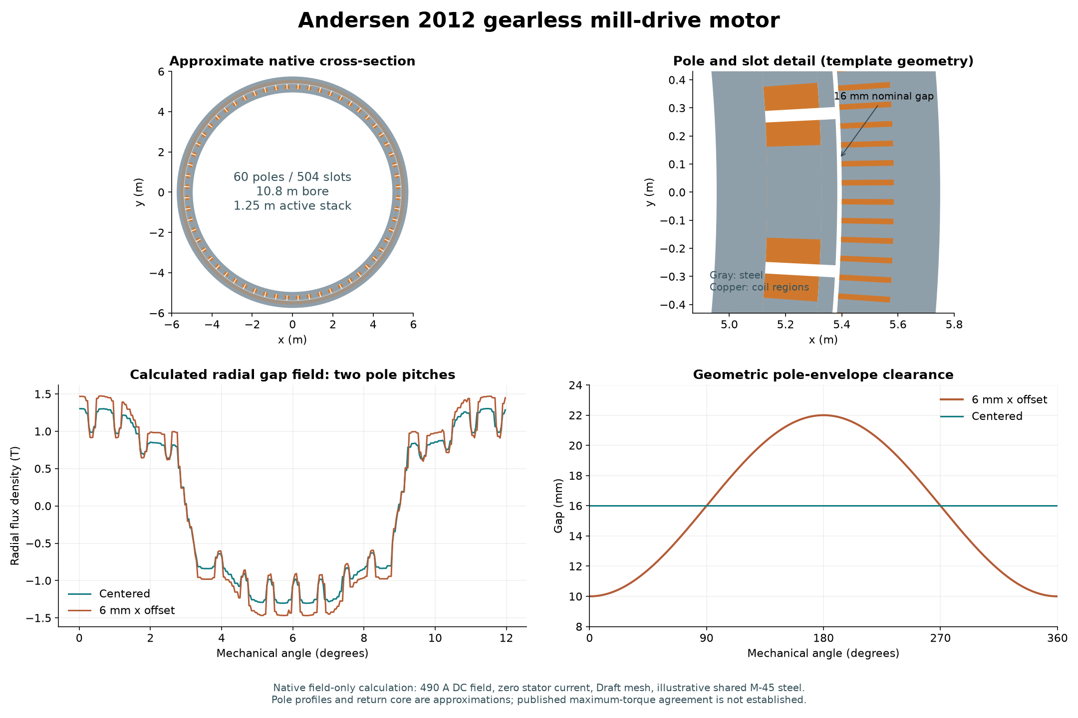
The input reproduces Table 3.1’s winding connections: a 10-slot coil span and an 84-slot base winding repeated six times. Fig. 5.4 and Table 5.1 supply rotor and stator dimensions. These dimensions define an approximate cross-section in Motor Maven’s wound-field template.
The native model uses an annular rotor core, simplified pole profiles and open slots. It uses the illustrative FEMM M-45 curve for both steels; the thesis specifies St.42 rotor steel and M400-50A stator steel. Its field-only default differs from the thesis’s maximum-torque condition, which includes 2,480 A RMS stator excitation. The published 259.9 kN attraction per pole, 13.6 MNm torque and derived 255.554 kN/mm lateral sensitivity remain separate reference targets. Agreement with those values is not established.
Source, assumptions and numerical reference checks
Andersen’s DTU thesis record: Section 2.2 (printed pp.8–9) supplies field excitation and coil packs; Section 3.2/Table 3.1 (pp.18–20) supplies the winding; Table 3.4 (p.31) supplies active length; Fig. 5.4/Table 5.1 (pp.50–51) supplies dimensions. The 53 field turns follow 18 + 18 + 17 turns with three parallel copper rows.
The native phase labels A/B/C correspond to printed U/W/V to match the solver’s phase sequence. Pole widths become constant angular widths, and the active stack is uniform. An isolated central template placeholder does not represent a physical motor shaft. Supplied equivalent-circuit defaults are unused by the static calculation.
The reference checks retain centered, 6 mm eccentric and unexcited field-only calculations, including solver residual, weighted and contour forces, torque and clearance. They check the implementation at Draft mesh. At 6 mm offset, weighted-stress pull is 1.605 MN and minimum geometric gap is 10 mm; the independent contour force is 3.30% higher. These checks do not establish a converged, matched reconstruction of the thesis. Separate steel curves, pole geometry refinement and a loaded phase sweep are further work.
Published inputs and approximations (JSON) · Native numerical checks (JSON)
Try the standalone motor
In the development app, open Examples → Thesis examples → Andersen 2012 gearless mill-drive motor, then run the Wound-field lab. The unchanged bundled example is free to analyze; edits and numerical exports follow the Pro policy.
One Pro plan. Monthly or annual.
U.S. pricing: $9.99/month or $79.99/year, automatically renewing until canceled. Monthly and annual plans provide the same tools. Annual pricing saves about 33% versus 12 monthly payments. One-week full-Pro free trial for eligible Apple Accounts, once per subscription group; the trial renews at the chosen plan price unless canceled. Apple shows your actual eligibility, local price and billing period before purchase.
Opening and saving native project files remains available after subscription expiry. The app solves on your device and includes no analytics SDK. These web pages use Google Analytics as described in our privacy policy.
Know the model
Examples are illustrative. Material data, mesh and model assumptions affect results. The 3D induced-current solver currently holds the rotor stationary. Validate predictions for your application.