Static X-ray review
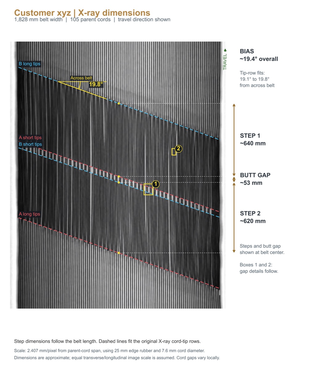
Review full-splice images, individual radiographs or image exports. Trace and number visible cords, examine the splice pattern, and estimate step lengths, bias angle and cord gaps where image quality and scale allow.
Independent engineering review
Already have X-ray images or scan video? Get a professional, independent review of your steel cord belt or splice with Andrew Hustrulid, PhD, PE.
Understand the cord layout, identify areas that need closer attention, and assess how the as-constructed splice shares load.
Static X-ray images · X-ray scan video · Splice analysis
Start with the data you have
For belt owners, operators, maintenance teams and engineers seeking an independent interpretation of existing inspection data.
Review full-splice images, individual radiographs or image exports. Trace and number visible cords, examine the splice pattern, and estimate step lengths, bias angle and cord gaps where image quality and scale allow.
Review a moving belt scan across successive frames to follow visible cord paths and locate areas of interest. Coverage, motion and image quality are assessed before deciding which observations and measurements the recording supports.
Original inspection exports give the best starting point. If you only have screenshots or a recording of a display, describe what is available so we can assess its suitability.
Expert splice analysis
Map visible cord paths and splice geometry. Identify irregular spacing, cord-end alignment and uncertain regions that need further inspection.
Compare the as-constructed splice with the supplied design or an agreed reference. Where the data supports it, use finite element analysis (FEA) to evaluate cord tension, rubber shear and the center of tension.
Review annotated images, measurements and calculations in a written report. A narrated video can help your team follow the analysis. The scope, assumptions and unresolved questions are made clear.
Example 01 · Report & video
This published, anonymized case compares an X-ray-based splice layout with an as-designed reference. Explore the complete assessment or watch the one-minute explanation.
Written assessment
Numbered cords, measured geometry, design comparisons and calculated load sharing, with the assumptions behind the results.
 Read the report English PDF · 10 pages
Narrated walkthrough
Follow the X-ray through cord identification, splice measurements and the comparison of cord tension and rubber shear.
1 minute · Narration and captions in English
All editions
Also published on LinkedIn: example report and narrated video.
Example 02 · Cord tracing from scan video
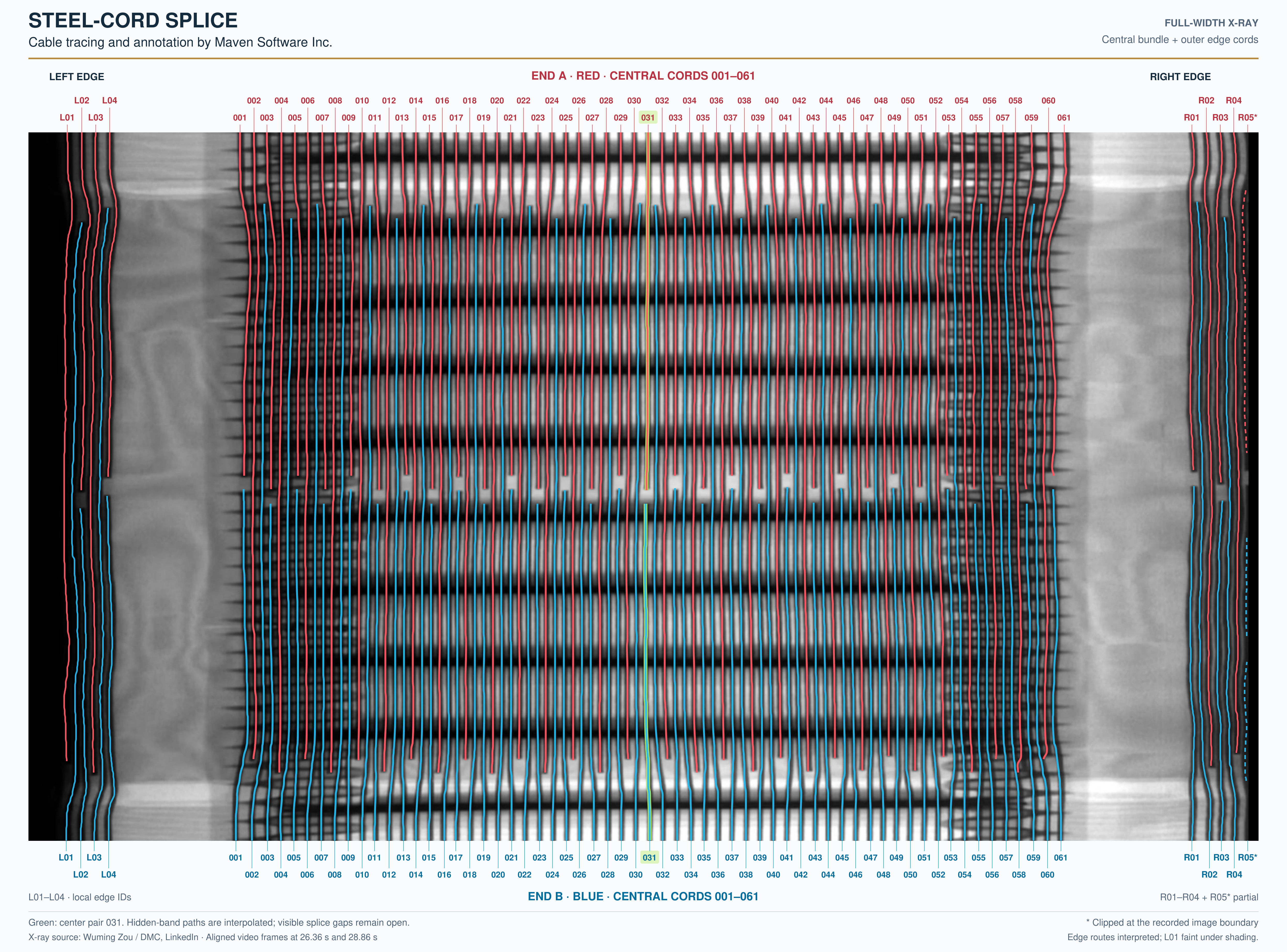
This sidewall-belt example combines two aligned X-ray video frames into a single annotated splice view. Maven's tracing follows the central cord bundle and the separate cord groups at both edges of the recorded image.
View full-resolution image PNG · 4976 × 3682
Paths across obscured bands are interpolated; partial and uncertain edge traces are marked. The colors identify cord paths, not stress or damage. This example presents a geometric tracing review; no load or strength calculation is shown.
Cable tracing and annotation: Maven Software Inc.
X-ray source: Wuming Zou / DMC, LinkedIn · Aligned video frames at 26.36 s and 28.86 s.
Example 03 · An unusual splice pattern
This unusual-looking splice raises a question about the geometry shown in the video. Maven traced and numbered 79 cords from each end to make the arrangement easier to examine.
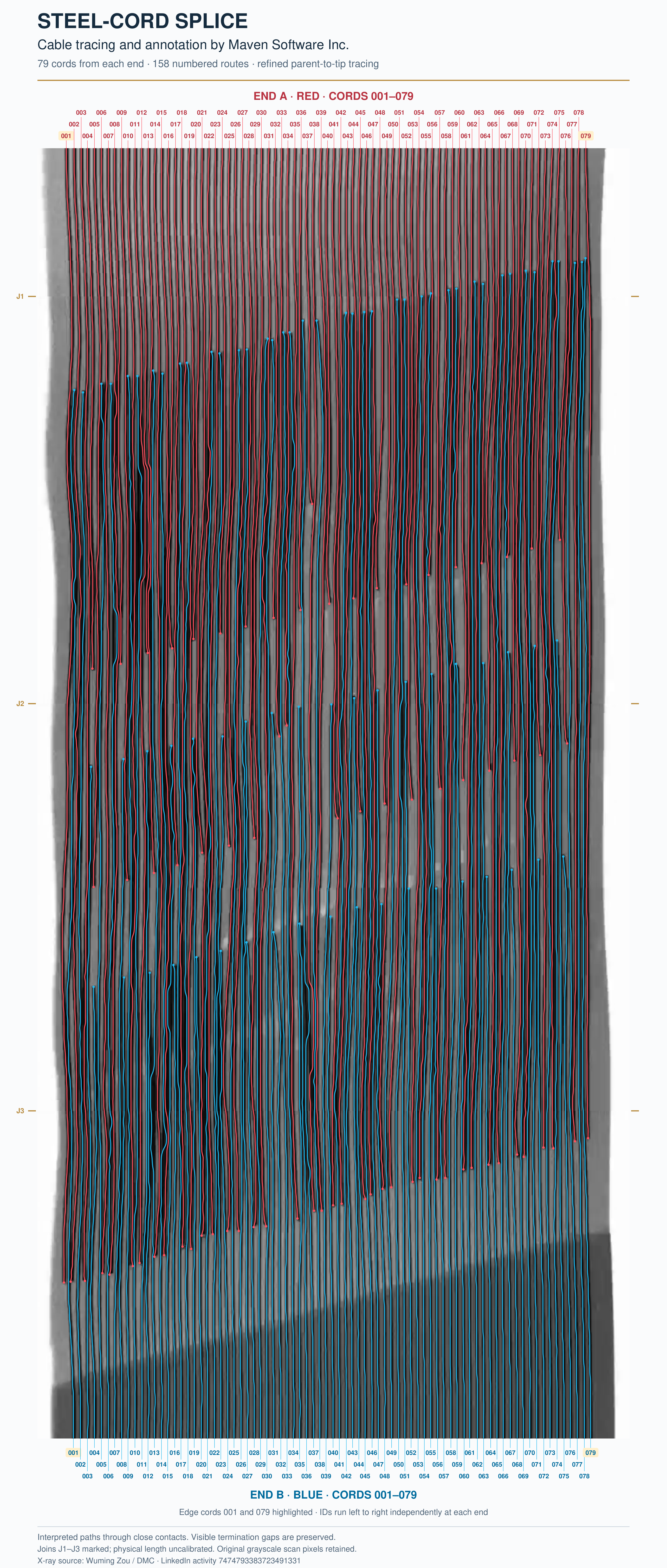
An unusual-looking steel-cord splice—it appears to have three steps, with a much shorter middle step. Is that the actual splice geometry, or an effect of the video capture? It would be interesting to see the original splice drawing.
Read Andrew's comment on LinkedIn
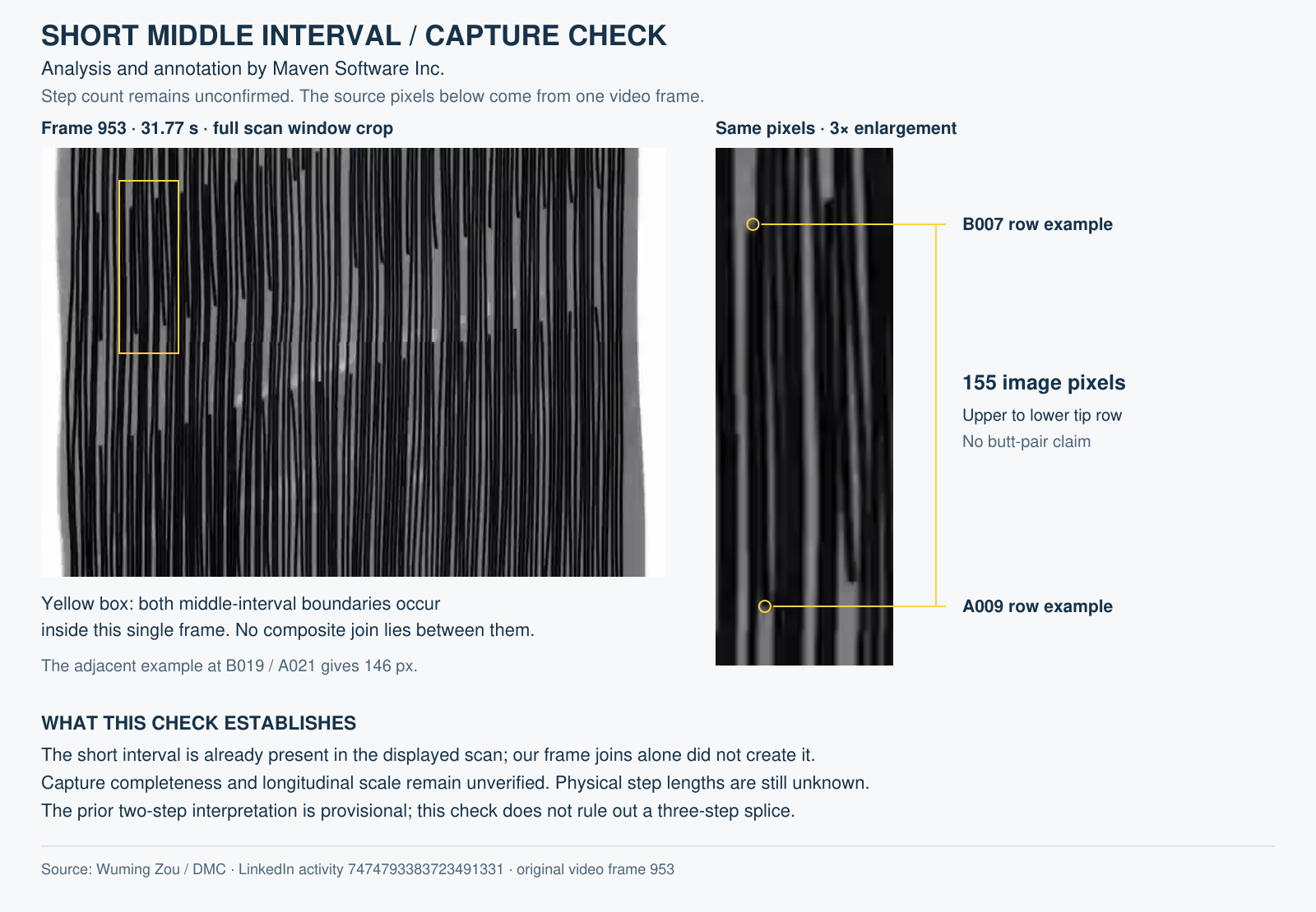
Both boundaries of the middle interval are visible within a single video frame at two checked locations. Our stitching did not remove middle rows at those locations. However, the scan advance and completeness are unverified, so the composite cannot establish the physical step lengths.
View numbered splice PNG · 2565 × 6030
A three-step interpretation is plausible; the step count and intended dimensions remain unconfirmed. This observation is not a finding of faulty construction. Cord paths are interpretations of compressed video, particularly where cords touch; colors identify the two belt ends, not stress or damage.
Cable tracing and annotation: Maven Software Inc.
X-ray source: Wuming Zou / DMC, LinkedIn · Selected frames at 31.43–31.97 s.
Request an independent review
Contact Andrew with a brief description of your X-ray data and the questions you want answered. We can then agree on the review scope, the available evidence and how to transfer the files.
Email AndrewAndrew I. Hustrulid, PhD, PE
Maven Software Inc.
andrew@hustrulid.com
You can start the conversation with incomplete information. We will identify what else is needed for a useful assessment.